
MODULAR FIXTURE SYSTEMS
One Modular Fixture System.
From Welding to Inspection.
A configurable tooling platform built around coordinated 2″, 1″, and ½″ grid patterns. Interchangeable blocks to build modular fixtures for welding, machining, casting, CMM inspection, and precision assembly with off the shelf components for application-specific needs.
MODULAR.
5/8 IN, 3/8-16, 1/4-20 HOLES
SCALABLE.
MILD STEEL & 6061 ALUMINUM
REPEATABLE.
ENGINEERING SUPPORT
THE THREE-TIER SYSTEM
One Standard. Three Grid Sizes.
A coordinated grid architecture designed to support tooling across manufacturing and inspection workflows.
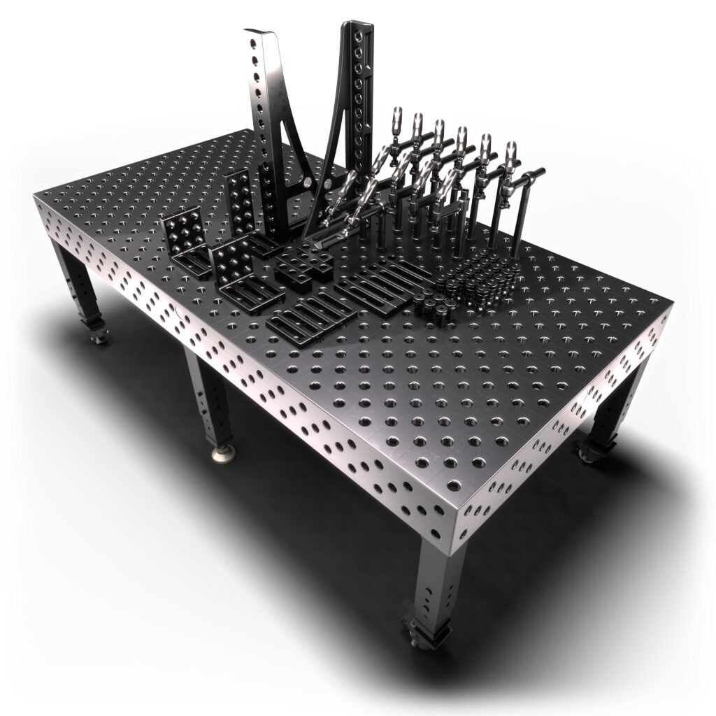
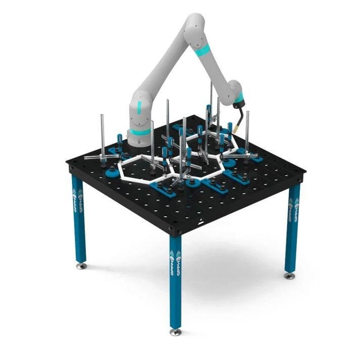
TIER 1: FOUNDATION GRID
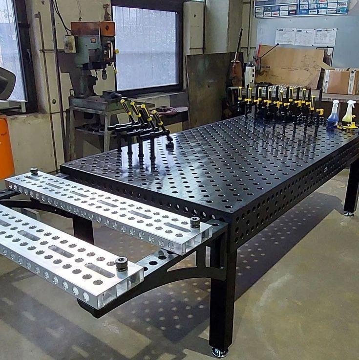
Weld tables and structural bases. 5/8 in holes on a 2 in grid, mild steel. Mount tool stations, frames, and robot arms.
- Pitch: 2.000″
- Heavy-duty welding-table-style foundation
- Base for larger production setups
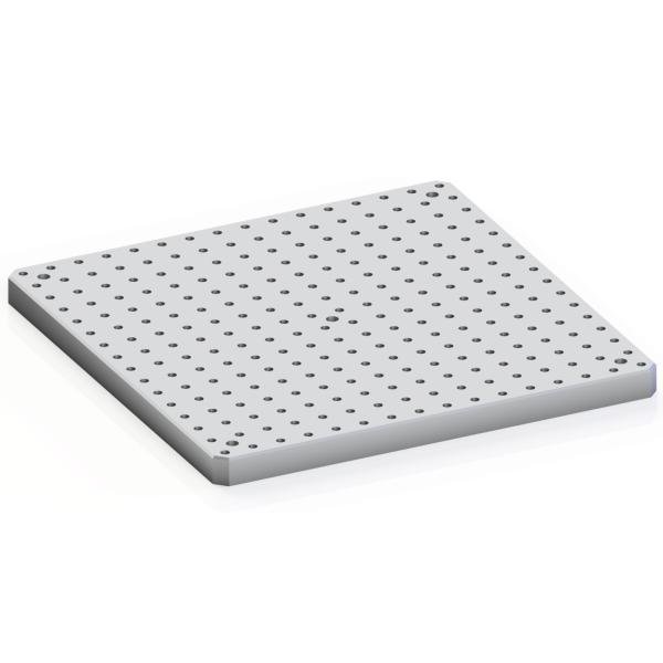
TIER 2: PRODUCTION FIXTURE GRID
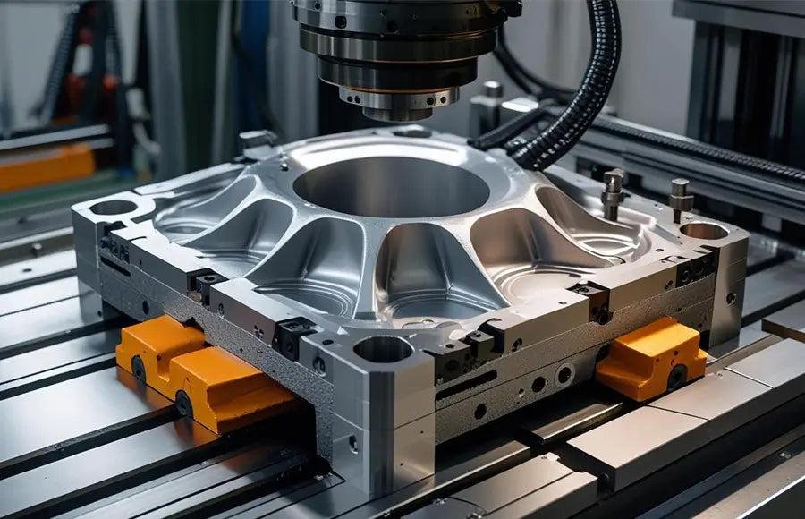
Machining and casting fixtures. 3/8-16 holes on a 1 in grid, 6061 aluminum. Datum blocks, locating pins, stops, and clamps.
- Pitch: 1.000″
- Modular fixture plates and workholding
- Configurable production fixtures
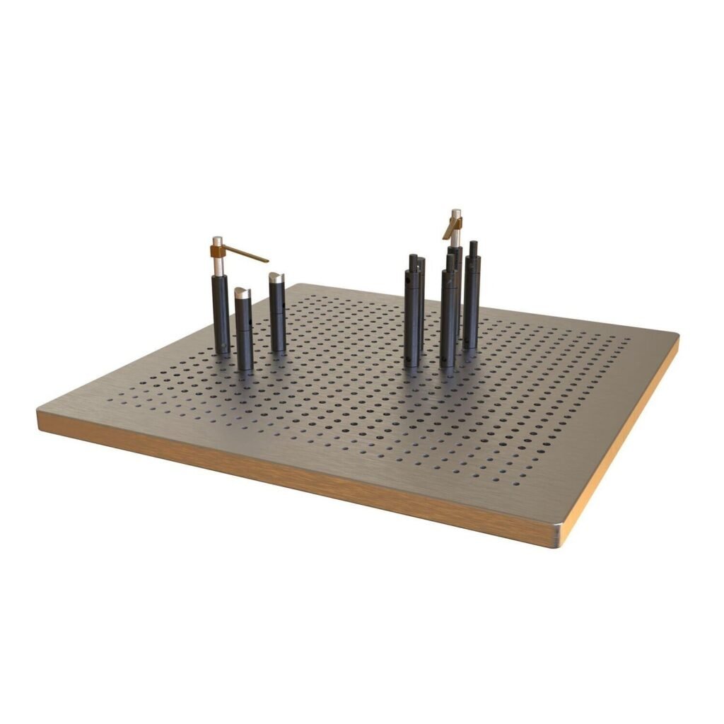
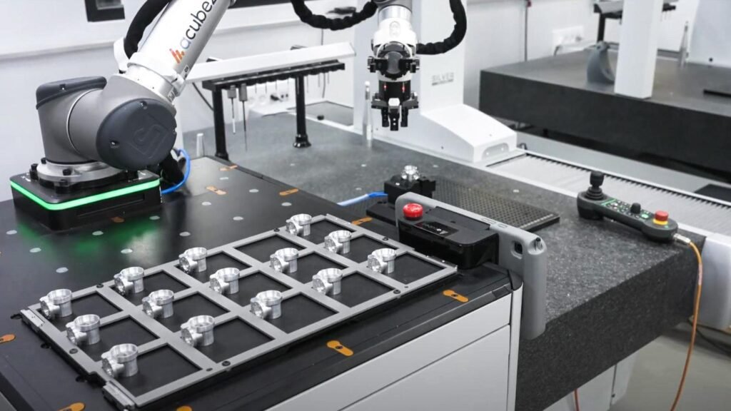
TIER 3: CMM & INSPECTION GRID
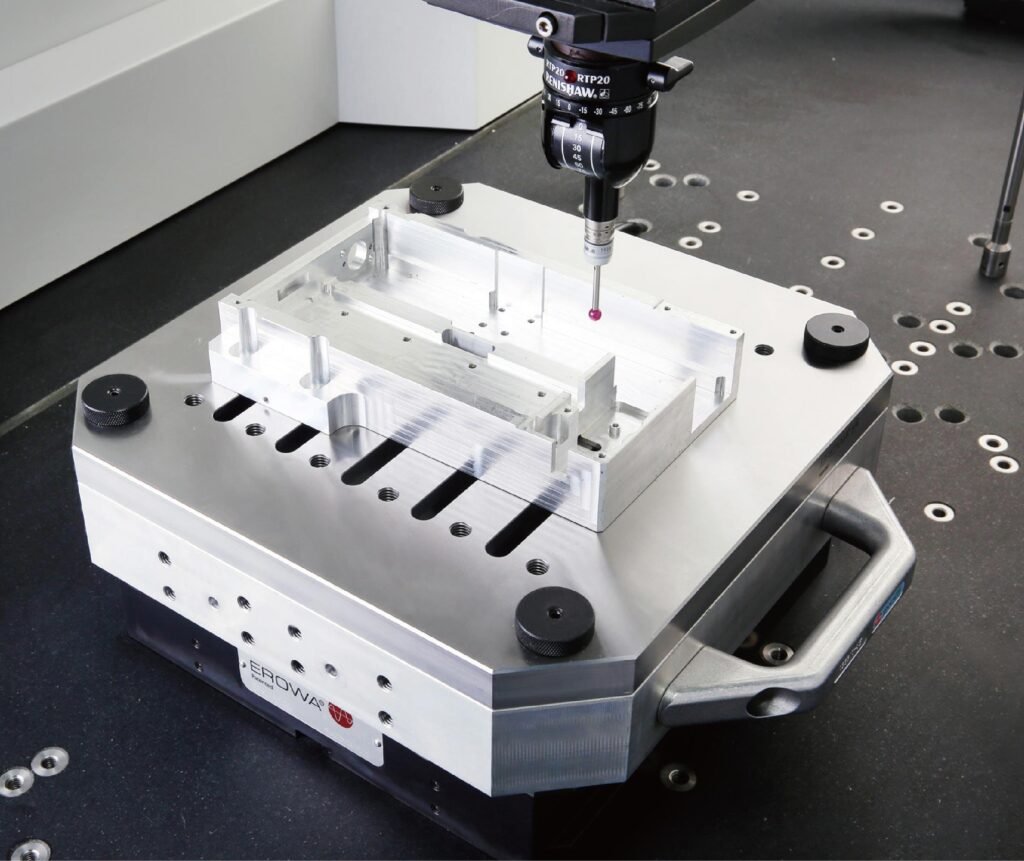
CMM and small-part inspection fixtures. 1/4-20 holes on a 0.5 in grid, 6061 aluminum.
- Pitch: 0.500″
- CMM and inspection fixturing
- Dimensional measurement setups
- Assembly and alignment applications

A COORDINATED MODULAR SYSTEM
Build Around the Work. Not Around One Fixture.
Configure tooling around the manufacturing task. The three grid sizes establish a common spacing hierarchy for developing fixture components and larger setups.
- Select the foundation or fixture platform.
- Define the required mounting interface.
- Configure the tooling for the application.
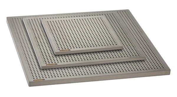
APPLICATIONS
Built for Real-World Manufacturing.
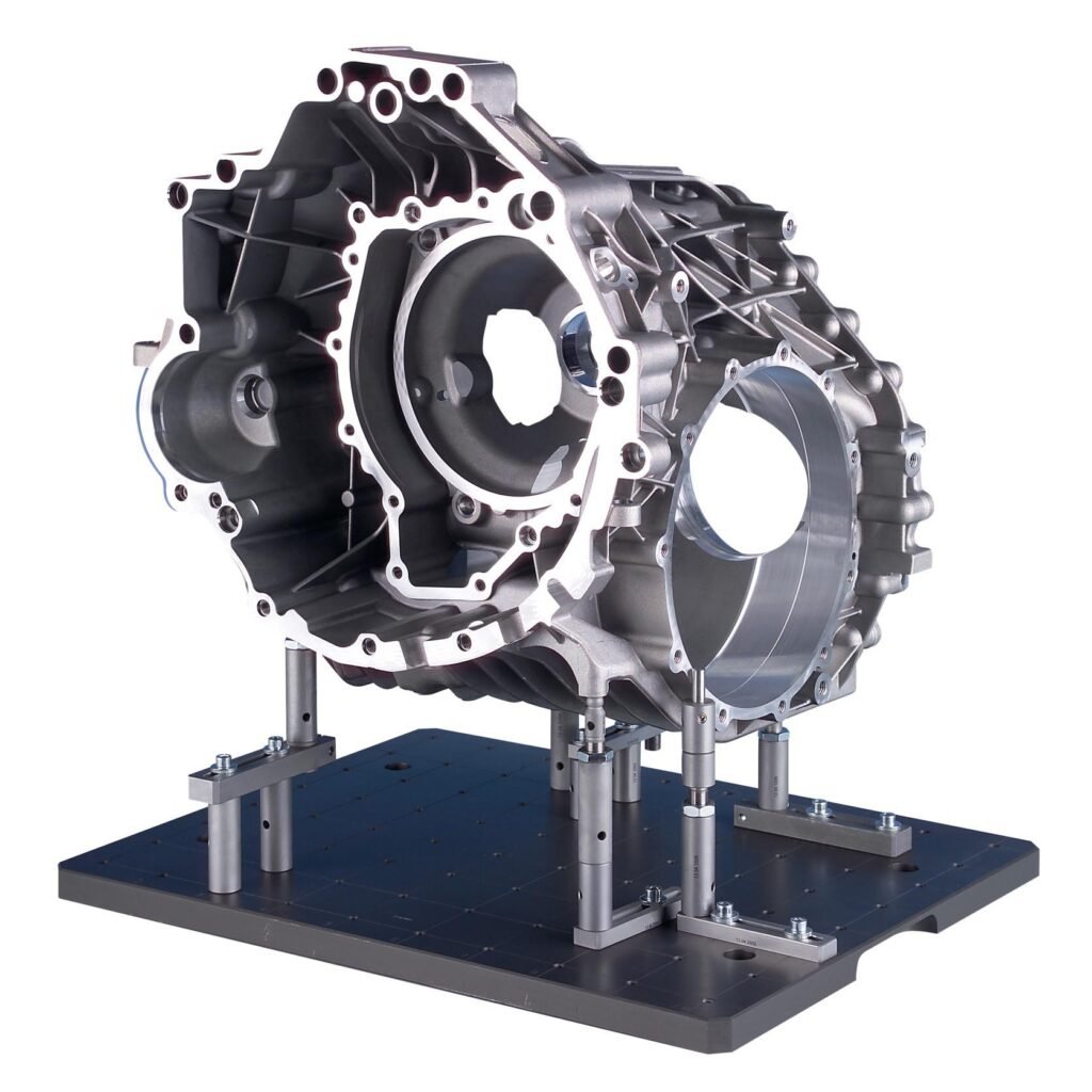
From casting and machining to precision inspection, modular fixture concepts can support a range of manufacturing and quality workflows.
CASE STUDY
Introducing a Modular Fixture with Plans for Full Modularity
A casting-machining project highlighted the challenge of relying on dedicated production and inspection fixtures for individual part numbers. The case study explores a modular approach intended to support reusable tooling and future system expansion.
TECHNICAL REFERENCE
Explore the Engineering Standard
Review the mechanical framework and developing interface principles behind the Modular Fixture Systems platform.
Frequently Asked Questions
The current architecture defines three grid pitches: 2.000″ for Tier 1, 1.000″ for Tier 2, and 0.500″ for Tier 3.
The system is being developed around a coordinated grid hierarchy. Direct compatibility between tiers depends on the final mounting interfaces, alignment, and fastener design.
Materials and configurations will be defined for individual components and projects. Contact us to discuss your application.
The product catalog is under development. Custom fixture inquiries are welcome while the initial component designs are being developed.
Use the contact form to describe your application, part, workholding requirements, inspection needs, and expected production use.
Have a Fixture Challenge?
Tell us about your manufacturing, workholding, or inspection application. We’ll review the requirements and discuss a suitable engineering approach.